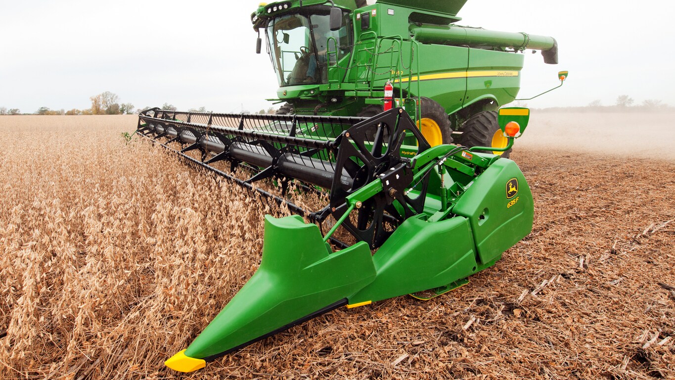
John Deere 635f Manual
May 21, 2013 - The process for locking up a 635F is very simple. 4) Manually lower the head to the ground to push the cutter bar to the full raised position where it. How do I align gears in my John Deere 995 rotary header read more.
Do this fiist. Vibration occurs while operating 600 series flex platform. Operator notices a vibration in the cab while harvesting with a 600 series flex platform. Check list for diagnosing platform vibration issues: 1. Check the backshaft speed. The platform should be operated at the lowest back shaft speed.
Check the mounting hardware for the knife drive gearbox. Disconnect the knife drive and verify that the vibration is with the platform and not with the combine. You may also try disconnecting the knife head from the gearbox and just run the knife drive gearbox to see if it is causing the vibration.
John Deere 635f Operators Manual
With the knife drive disconnected turn the gearbox over by hand and check for tight spots. The knife should operate smoothly.
Make sure that the knife back is not buckled. Check knife head alignment and verify the knife head is not in a bind.
The knife should run in the center of the guard. Check all of the knife hold-downs. Tcu student guide. Hold-downs should be adjusted so that a business card will fit between the hold down and the knife section. Make sure the drive belt aligned properly. Check for loose hardware in the stabilizer and cutter bar attachment area, or for a failed stabilizer weld joint on the diagonal stabilizer arm.

Also check for worn out ball joints and LH rear ball joint free play in the stabilizer. Additional Information: If the above checks have been made and the head is adjusted correctly and has no broken or loose parts, follow these steps: 1. If the customer reports that the vibration is acceptable when the head is on the ground and cutting, this is the best option: Install out of cut software onto the armrest controller with service advisor. For 2002 and later combines (695101– ) install armrest software 208044 version 5.5 or newer. The option can be turned on in address C00 104 (bottom line, 3rd digit) after software is installed. If the complaint is mostly the mirrors shaking then install washers between the isolator clamp and ladder rail support. One washer should be installed on every bolt that holds the isolator clamp.
Order 8 of any one the following washers; 24M7054, 24M7267 or 24M7088. If the machine is still vibrating, order and install slowdown knife drive sheave through service parts AH216410 - (Gold) 625F, 630F AH216411 - (Silver) 635F for machine xxxxxx - H64 H221001 - 635F for machines H65 - xxxxxx (1-3/8” heavy duty back shaft & cast sheave) 495 rpm slow down sheave. H227540 - 635F for machines H65 - xxxxxx (1–3/8” heavy duty back shaft & cast sheave) 480 rpm slow down sheave. 3.If vibration persists, an Auger Arm Kit is available. The kit will help support the end sheet to reduce vibration. For documentation purpose, please continue to enter “REPORT ONLY” DTAC cases for machines needing the kit.
The kit number is AH223626 and the instructions are H224801. If there is improvement, but still not satisfactory, a Right Hand stabilizer kit is available. The kit number is AH225360 and the instructions are H226596.
This will adapt to fit all 600 series flex platforms. This RH stabilizer is standard on MY 07' 635F machines, H00. Note: For more information regarding Left Hand stabilizer parts, please reference DPAC solution 75016.
To reduce cab vibration, a cab anti-vibration kit can be installed. The kit number is AH222406 and the instructions are H223989. Note: Vibration severity should be judged only after these steps are followed, and the machine has been ran under load (if possible) with the header on the ground. Vibration should NOT be judged with the head up while on solid ground because this is a designed over-speed condition not relevant to header performance in the field.

OMH227052: 600 F and 600 R Series Cutting Platforms, Block File: MH8881902MAY05.htm Header Height Sensing › HYDRAFLEX Heads with Auxiliary Sensors Auxiliary sensors on HYDRAFLEX heads allow using Header Height Sensing when cutting wheat or other standing crops with the cutterbar locked into the rigid position. The sensors allow using automatic height control in a cutting range of 100 - 350 mm (4-14').
On heads equipped with auxiliary sensors, a sensor connector (A) identified with yellow marking tape is located at the header frame where the hose bundle for the single point hookup (B) meets the top beam. When this connector is plugged in, the HYDRAFLEX head uses only the auxiliary sensors. In this mode, both calibration and operation are identical to a rigid head. Whenever this connector is unplugged, both calibration and operation are identical to normal HYDRAFLEX operation.
John Deere 635f Platform
NOTE: Header calibration is required whenever the auxiliary sensor plug configuration is changed. See Header Calibration in Calibration Procedures. An additional hybrid mode of operation is also possible using auxiliary sensors. This allows Header Activation Button 2 to operate in a hydraulically locked (rigid) mode and Header Activation Button 3 to operate in the flex mode. Enabling this feature requires a change in diagnostic address E01-171. (See your John Deere Dealer.) A-Sensor Connector B-Hose Bundle MH888 -19-02MAY05-1/1.